
Project profile
|
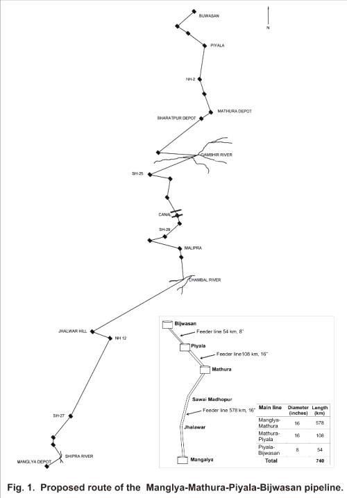
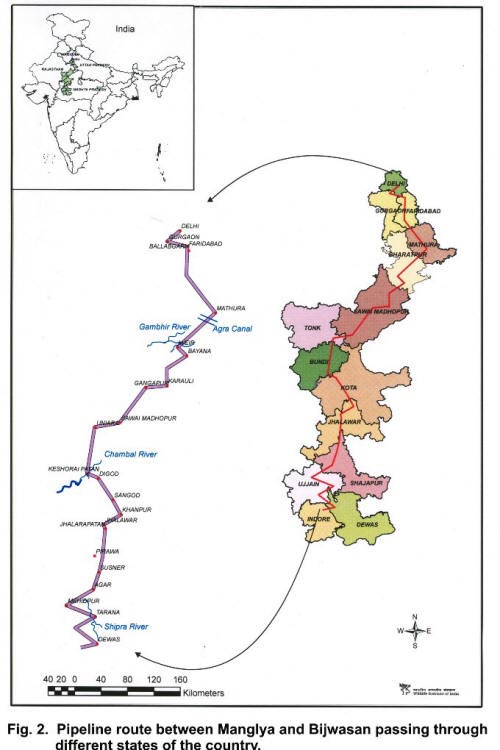
The project envisages laying of 740 km long cross country pipeline from BPCL’s terminal at Manglya (Indore) to Piyala terminal which is proposed to be developed adjacent to the existing LPG bottling plant at Piyala in Haryana and a 54 km long feeder pipeline from Piyala to Bijwasan for the movement of MS, SKO and HSD from Mumbai refinery. 2.1 Project justification The project will help BPL create better negotiating strengths for products/tariffs with oil marketing companies. The project will be beneficial for meeting the petroleum product demand more competitively in the Northern Region. The project will help in smooth evacuation of Mumbai Refinery The project will reduce rail/road and reduce hazards of environmental pollution associated with transportation of products by road or rail. Reduced consumption of petroleum products due to reduction in vehicular traffic once the transportation of petroleum product is ensured through pipeline. 2.2 Pipeline length, route and major crossings Table 2.1 Pipeline route through different states and districts in India.
The following are the major crossings along the pipeline route: Railways - 17 National Highways - 10 State Highways - 23 Major River - 11 Canals - 33
2.3 Pipeline design parameters The following are the design specifications and parameters for the proposed pipeline:
The line pipe shall conform to API specification 5L. The grades and size of line pipe shall be API 5L Gr. X-60 and 16” NB for Manglya-Piyala section and API-5L Gr. B & 8” NB for Piyala-Bijwasan. Pipe wall thickness shall conform to ASME B31.4 and shall also meet the requirements of OISD 141. All pipeline materials downstream of the main line pumps, such as valves, flanges and fittings etc. shall be of Class 600# rating. 2.3.1 Location and design features of sectionalising valves and station block valves The throughput estimates for the Phase-I of the project have been made for the year 2011-12 which is assumed as 2.2 MMTPA for Manglya to Piyala and 1.0 MMTPA from Piyala to Bijwasan. However, the pipeline optimization and selection of the size has been done considering the projected throughput of 3.5 MMTPA for 2019-20. A pump configuration of one main & one standby pump at Manglya and one main and one standby pump at Intermediate Pumping Stations for particular pipeline size has been considered for the optimization study. Adequate number of sectionalizing valves (27 nos.) and Station Block Valves shall be motor operated, All sectionalizing valves shall have provision for remote operation (ROV). The sectionalizing valves shall be buried and provided with stem extension. The mainline valves shall be full-bore type ball valves to allow smooth passage of scrapers or pigs through them. These valves shall conform to API-6D. In addition to the above, two sectionalizing valves shall be provided for segregation of feeder pipeline at strategic locations. Pig Launching facilities at Manglya Terminal, Pig Launching and Receiving facilities at IP station, Mathura Installation & Kota and Pig receiving facilities at Piyala will be provided to facilitate effective monitoring of the pipeline condition to enhance safe operation of 16” diameter pipeline from Manglya to Piyala. Pig launching facility and pumps at Piyala installation and Pig receiving facilities at Bijwasan installation shall be provided for 8” diameter feeder pipeline. Pipeline and associated facilities shall be constructed in accordance with ASME B 31.4 and other applicable API standards. The pipeline shall be laid underground with minimum 1 m cover. Additional cover, wherever required, shall be provided in accordance with OISD 141. Welding shall be carried out as per API 1104. All welds shall be 100 % radio -graphed. After the installation is completed, the entire pipeline shall be hydrostatically tested. The hydrostatic test pressure at any test section shall be 1.5 times the design pressure. Hydrostatic testing of terminal piping shall be carried out separately. 2.4 Construction methodology Table 2.2 Different spreads of Manglya-Bijwasan pipeline.
The pipeline will be laid with a minimum cover of 1.0 m below the ground level and the land will be reinstated to its original land use after completion of laying the pipeline. In general, the pipeline will be kept at a minimum distance of 100 m from any organized habitat to avoid rehabilitation and resettlement issues associated with the project as far as possible. The width of Right of Use (RoU) will be 18 m and will be reduced at places wherever restrictions dictate reduction in RoU. For the construction of main pipeline in different type of strata and installation of associated pipeline crossings, the following methodology has been considered: Common land crossing Rail Roads & canals Minor river crossing Major river crossing For river crossings, lowest bed level shall be calculated after giving due consideration to scour depth of such water crossings. The pipeline shall be concrete coated, if required, to provide sufficient negative buoyancy. Corrosion inhibitor will be used along with the products to be transported to protect internal corrosion. 2.5 Safety features and measures Cathodic Protection System External pipeline protection will be a combination of corrosion coating and cathodic protection techniques. During the construction phase, the pipeline will be protected by temporary cathodic protection using sacrificial anodes, with a design life of 2 years. Permanent cathodic protection system for the pipeline shall be by impressed current method, with a design life of 35 years. A dedicated low capacity optical fiber cable link is envisaged to provide data communication and voice communication link between dispatch terminal, receiving terminal, en route Top of Points (TOP’s) and Sectionalizing Valve (SV) Stations. This shall be hooked up with the existing tele-communication system of Mumbai-Manglya pipeline. Supervisory Control and Data Acquisition (SCADA) Leak detection Fire prevention and protection measures 2.6 Description of Piyala terminal and storage tanks MS : Floating roof SKO : Floating roof HSD : Floating roof Slop : Cone roof Four tanks each shall be provided for MS and HSD and 2 tanks for SKO. Two tanks each of MS/HSD shall be used for storing Bharat Stage II product which is required for feeding up all northern locations and balance two tanks each of MS/HSD shall be utilized for storage of Euro 3 equivalent specification product for feeding Delhi/NCR markets. Tank to tank transfer facility shall be provided using products transfer pumps. |
| Inside Cover | Acknowledgements | List of Plates & Figures | Introduction |
| Project profile | Methodology | Baseline Status | Impact Prediction |
|
Conclusions and Recommendations |
References | Annexures |
Last Updated: November 14, 2015